Gate(way) to Shelly
I did promise another post Soon™ didn’t I? Well here it is.
The very first thing I wanted to control with my new zest for home automation is the entry gate to our home. The motivations are simple:
- Link it to exterior lighting so I can automate us not having to walk in the dark when getting home late
- Provide guest access without buying and programming in more remotes
- Allow remote access for deliveries when I’m not home
- Undeniable cool factor and nerd cred
Now, my gate motor is the ET-500, named imaginatively by E.T. Systems who are now part of some Italian conglomerate. It is quite likely the most popular sliding gate motor on the South African market and has been for some time. So I hope this post will help people who want to setup something similar at their home.
As with the previous post, this will be focussed on the HomeKit firmware of the Shelly devices and their garage door mode. Hardware wise there is no difference, but on the software side I believe there is something similar in the stock firmware. Regardless, this mode has the following core functionality:
- Relay pulse to open gate/garage
- Sensing of gate/garage state from external sensor

These settings are exposed on the Shelly HomeKit web UI where you can tweak the expected movement time, pulse period, as well as what type of closed sensor you have. The settings you see above are what works for the ET-500 and the setup I’ll describe in the rest of the post, except for movement time. Movement time is used by HomeKit to put an upper limit on how long it should wait before expecting the closed signal. If it does not receive a closed signal, it will provide you with an alert that the gate is not fully closed and their may be an obstruction or malfunction. To set this parameter, simply time how long it takes your gate to go from fully open to fully closed. In my case I added an additional second to the total for some more leeway.
Before I dive into specific wiring for the ET-500, let’s take a look at the wiring diagram in the Shelly application notes. For our specific application the wiring will be nearly identical, except the ET-500 runs at 12V internally, and we should switch the Shelly likewise to that voltage before continuing.
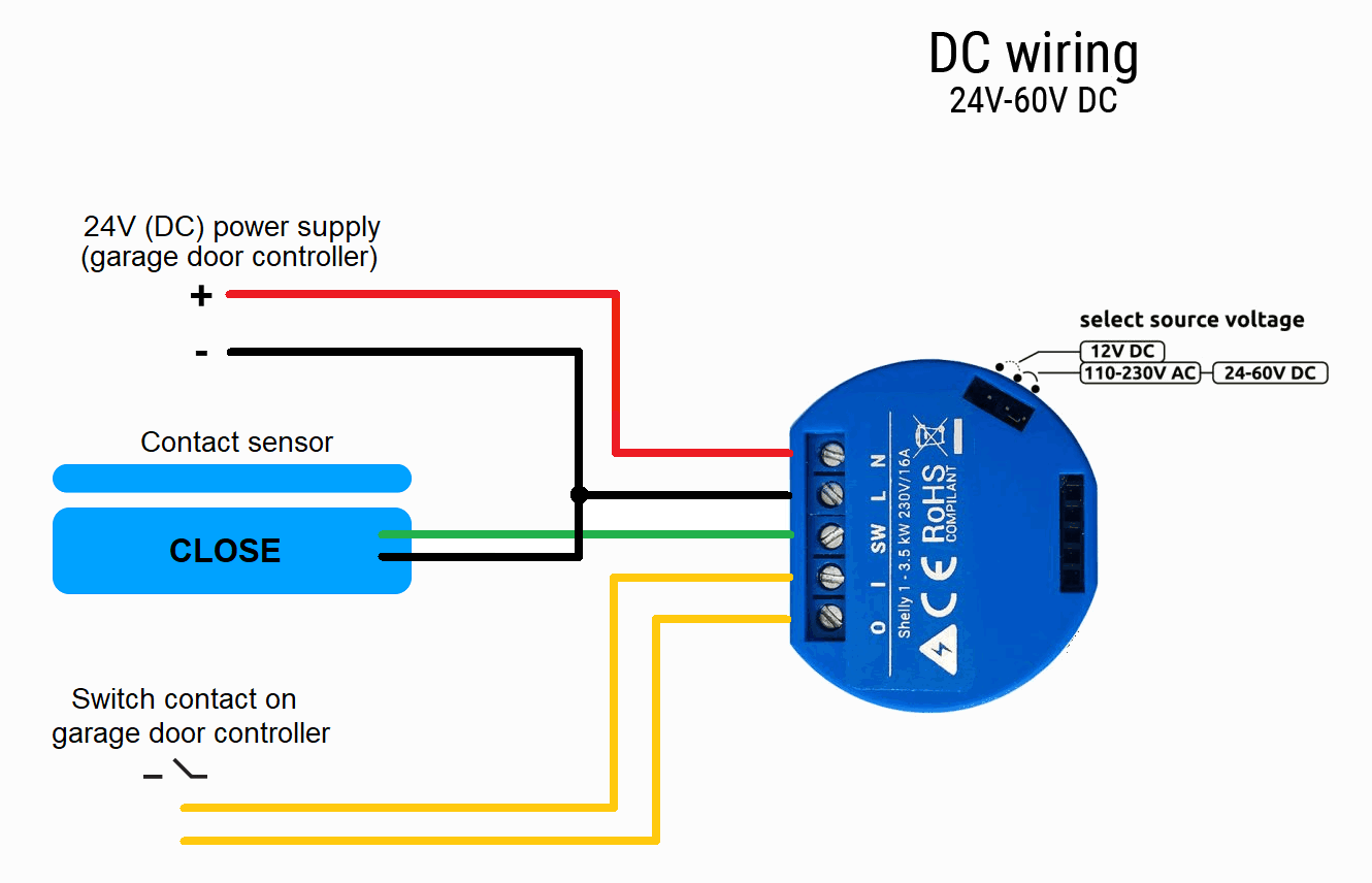
We now have a general idea of what we need to look for in our gate motor:
- Some point to tap off 12V
- Connect to the existing gate closed sensor
- Connect to some input on gate controller to make it open up
Before I go and sit outside in the sun, rain or relentless risk of people looking at me, a quick google nets us the installer’s manual of the ET-500 and, handily, has a visual pinout guide. At first glance it appears that we won’t have much of a challenge, there is a 12V supply (PL3), there is an input for full travel trigger (BT), and there is a closed limit input (LC).

However, this closed limit is not a mechanical switch input, but some sort of two wire magnetic sensor. This will need some examining of the circuit to determine what the best course of action would be.
Looking at the circuit and doing some probing reveals a very interesting configuration. There is an indicator LED that illuminates when the sensor is triggered. The sensor appears to be fed with 5V. When the gate is closed, the measured voltages on the sensor pins are near zero. When open, the one pin reads 5V. Such mysteries.
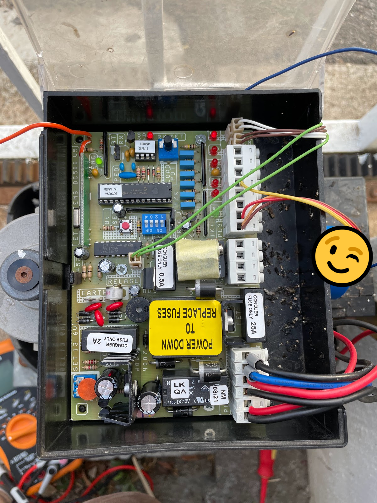
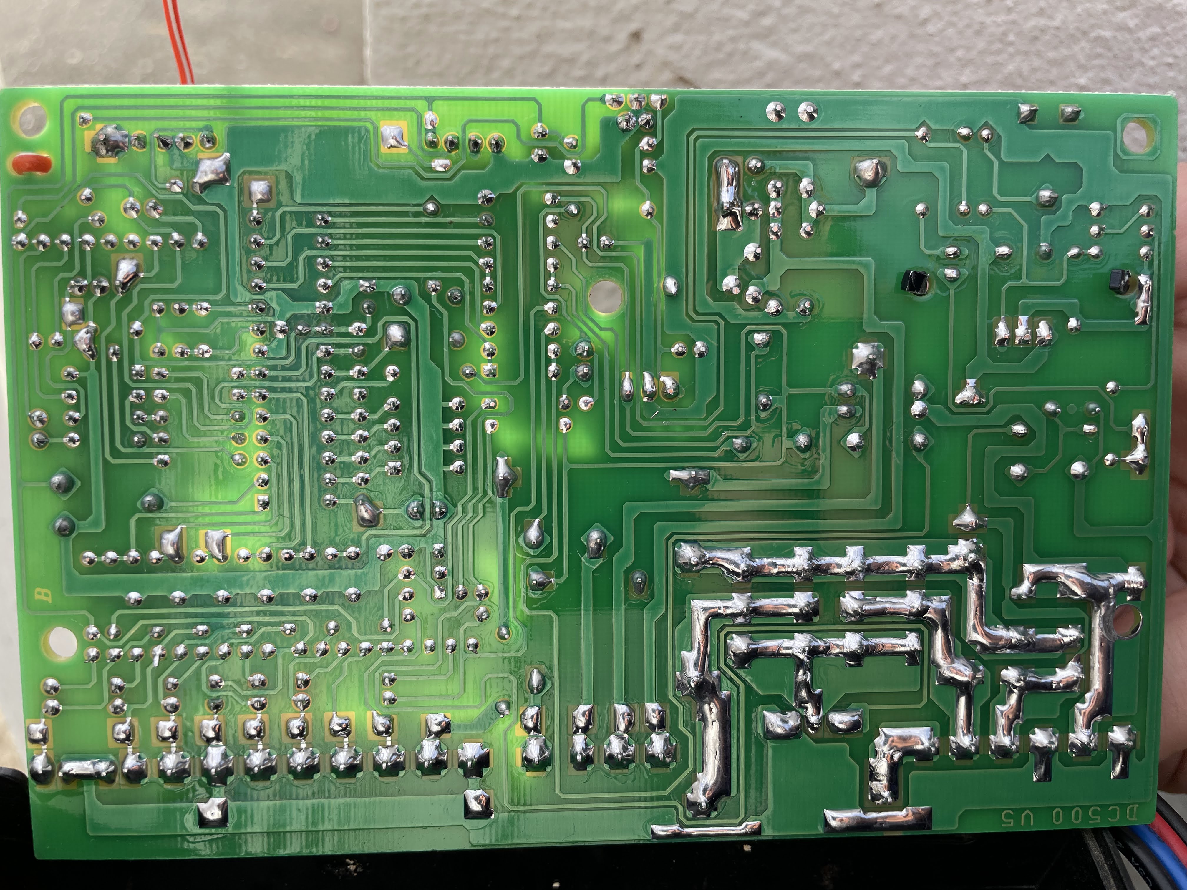
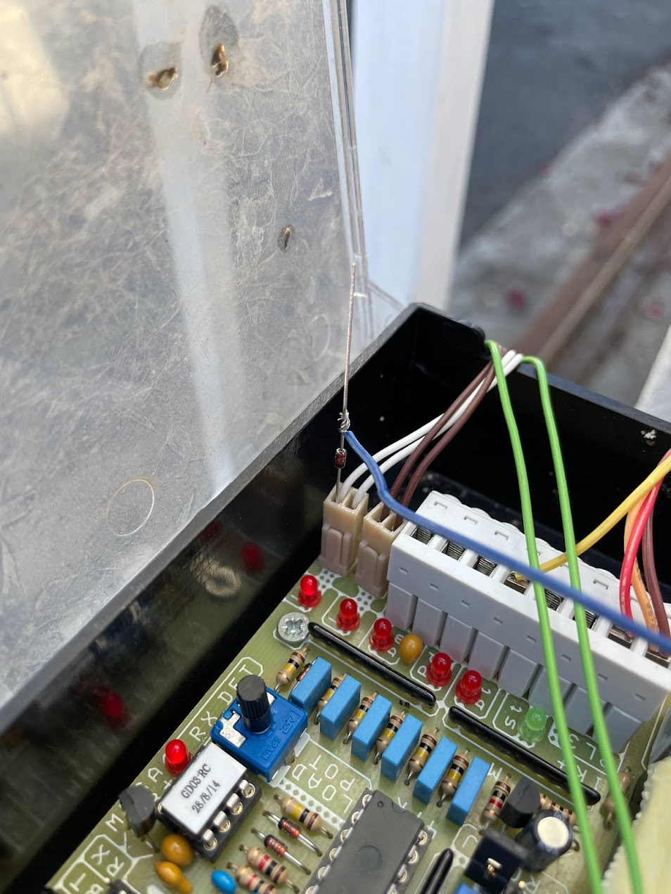
Taking a closer look at the actual controller PCB as shown above, it’s clear that it’s a single layer board with all traces on the reverse side. This is fortuitous as with some image mirroring, perspective correction, and opacity, we can quickly overlay the two sides and rapidly trace out the circuitry related to the closed limit switch as shown below (controller to pin path shown in red at the bottom right corner):
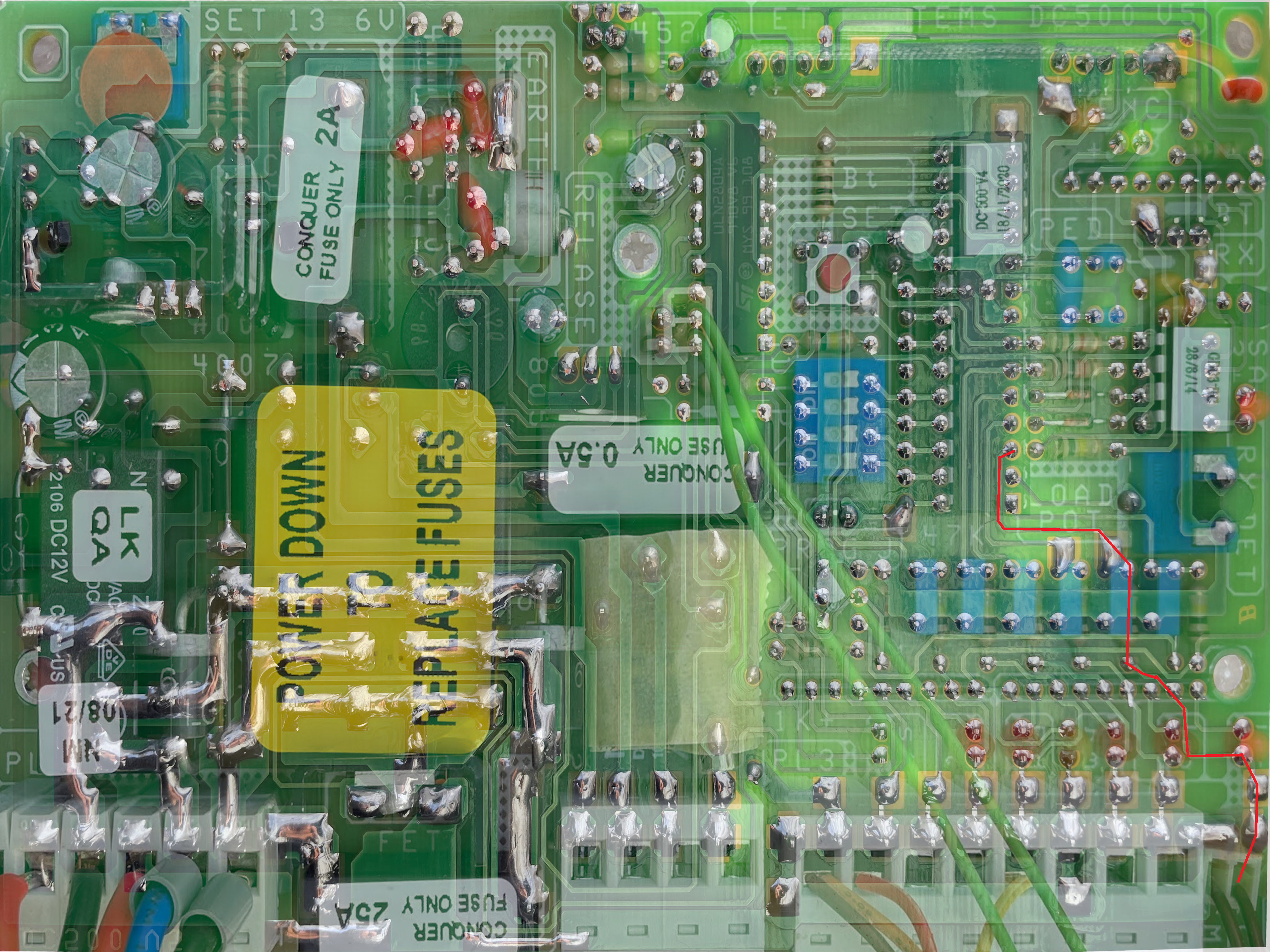
Decombombulating this a bit further gives us the simplified diagram as shown below, of quite a clever circuit. The magnetic switch operates much like a traditional switch, which makes me think it might be a reed switch, going from open circuit to short depending on magnet position.
The LED which indicates whether or not the switch is closed is fully independant of the gate microcontroller. When the switch is open, voltage at both sides of LED are pulled up to 5V through the two resistors (part of resistor networks in this case). The voltage at the cathode side of the LED is sensed by the input RA1/AN1 of the PIC microcontroller through what appears to be a button debounce circuit consisting of a capcitor and 100kΩ resistor (further supporting the idea of a reed switch).
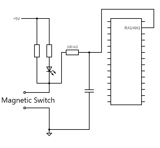
When the switch is closed, cathode side voltage is pulled down to ground, the LED starts passing current and glows, and the controllers sees the state change on the input pin. Now, all of this is operating at 5V, and we’ve seen from the previous blog post that the Shelly is outputing ~3V on the SW pin under these voltage conditions. So how do we safely connect this to the switch pins?
I’m not too worried about the Shelly damaging the gate controller (though it would be an expensive exercise to replace), but 5V could potentially flow into the Shelly and cause some issues, so the first thing that came to mind is to just put a diode between SW pin on the Shelly and the LED cathode side pin of the magnetic switch.

Some quick and dirty testing shows that this worked excellently! The SW pin is pulled low when the gate is closed and the Shelly is protected from any reverse current flow (however unlikely) into the SW pin. Any small diode will do really and this one was randomly chosen out of my box of unorganised parts.
Some soldering and heatshrink makes this a nice permanent addition to the gate motor. The pin of the diode is kept in place via friction within the limit switch connector. To actually actuate the gate, the BT pin get’s connected to one of the relay pins on the Shelly, and the other to ground. When the BT pin is shorted to ground the gate will open, close, and stop as if controlled by a standard remote.

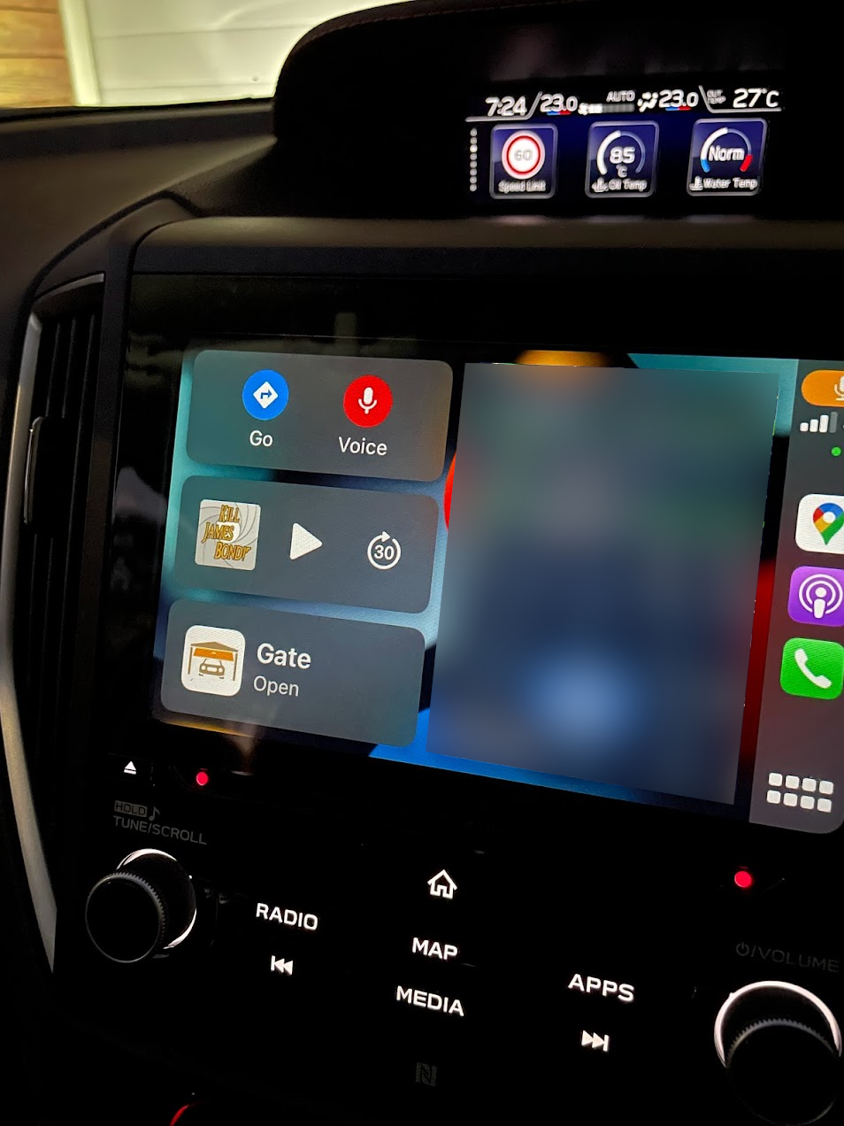
As shown in the previous post, this now allows for full control and state sensing of the gate by the Shelly through HomeKit. What I didn’t expect was the additional integration with Apple CarPlay! In hindsight, this would be obvious considering how Apple likes to do things, but I was inordinately pleased when I got home last night and the option popped up to open the front gate.
I hope this helps everyone else who might have this specific model of gate motor, or provide some inspiration for decoding the mysteries of your own gate motor.